 I acquired this really nice Apollo MK II. One of the coolest things about this bicycle is the Fred Deely HeadBadge. I understand these bikes were common on the West Coast but this was the first I have seen in my region. Apollo bicycles were made in Japan and sold in Canada by Deeley Cycles out of Vancouver.
The Apollo MK II is nicely equipped with Suntour components including a V-GT Luxe RD, Compe-V FD, power shifters, Sugino Maxy Crank and BB, Dia-Compe brakes and levers, Shimano high-flange hubs and ARAYA rims.
 |
 |
 |
The shifters were stem mounted Suntour Power Shifters. These shifters were designed to offer minimal resistance when shifting into a lower gear. It achieved this by employing a ratchet wheel and spring loaded pawl. When the lever is in its desired position the pawl and friction from the [screw] would hold the derailleur in gear nicely. To shift to a higher gear the rider would push the lever forward and the pawl would rotate the wheel breaking the friction allowing the derailleur to drop down into a higher gear.

Whether it was due to this type of shifter design or the concept of keeping both shift levers operating in the same direction while shifting to lower gears, the front derailleur cage moves inward or down when the lever is pulled moving the chain to the smaller (lower) ring. This takes some getting used to but I tend to like the concept. To me, it feels easier and smoother to pull the chain to the lower ring than push it to the larger. [Click picture at left for video on shifter actuation]
While completing a restoration it is customary to disassemble most parts to clean and inspect and/or learn about the bicycles history and design. Such was the case with these shifters. Most mechanics will carefully disassemble and reassemble in a very methodical way keeping the parts in order. However on occasion the reassembly goes awry and there is a need to consult technical diagrams and pray that someone on some forum, some where has encountered the same issue and resolved it successfully.
 The problem I was having was that the right shifter was ratcheting in the wrong direction. I looked to be assembled correctly yet did not hold the lever in place causing the RD to drop into the highest gear when the shifter was released. It seems that whatever information you find does not refer to the exact model you're working with. So I went with logic and knowing that the shifter ratcheted down.
The problem was an incorrectly positioned pawl and spring. I reversed the pawl and spring and although this orientation seemed the less likely one, it was in fact correct.
So if you find yourself in a similar situation, here are my notes and advice:
1. Do try to keep everything in order.
2. It does not seem to matter which way the ratchet wheel goes. Teeth up or down does't matter and the depth of the depression on the ratchet wheel seems to be the same on both sides. I did however face the teeth downward at the pawl. It seemed to make sense to do it this way.
3. The are two different size (diameter) slotted washers (#8 & #12). the larger one goes on the inside of the ratchet wheel. The chamfered side facing the stem. The "washers" are thick unlike the "spacer spring (#11) which are very thin.
4. On the diagram #9 "slot washer" doesn't look like a slot washer.
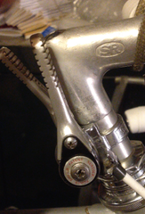
 In this particular style of power shifter the lever housing is symmetrical, meaning the position of the pawl and spring can easily be changed to an incorrect configuration. This photo shows what worked in this case. Looking closely at the orientation of the teeth one can see I choose to orient them down. This seemed like the more logical position allowing the pawl to ratchet over them as the lever is moved down.
After a 14 km test drive everything is shifting great. I'm looking forward to getting some miles in on this one before someone makes it their own. If it hangs around too long I may need to paint it and call it mine!
